
Home / Aluminum Flood Barriers / 55.12–78.74 in Protection
CUSTOM ALUMINUM FLOOD PROTECTION
Aluminum Flood BarriersUp to 78.74 in. (2 m)
55.12–78.74 inReusable aluminum stop-log barriers for projects requesting heights from 55.12 to 78.74 inches, approximately 1.4–2 meters. Review the 2.76-inch panel profile, posts and supports as one configuration for your entrance or boundary. Confirm the supported water conditions for the proposed height, span and site before ordering.
Free project review · Custom dimensions · No obligation
Higher manual model: US$899 per square yard, confirmed October 27, 2026. Confirm the selected model, billable dimensions and included scope in the written quotation. See the pricing basis →
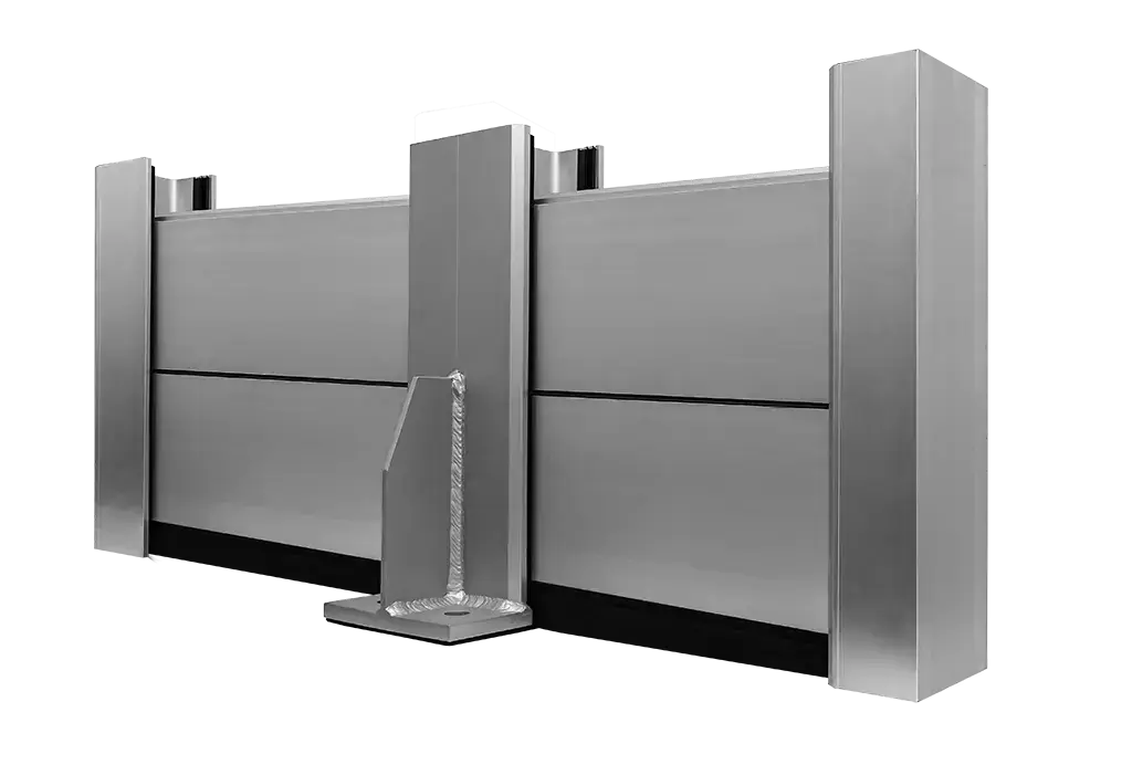
Start with your projectMatch the height, opening and support layout to your site.
IS THIS THE RIGHT CONFIGURATION?
When to review a barrier up to 2 meters high.
Start with the proposed height and opening width, then review the mounting surfaces, supporting structure and space for any posts or braces. A 2 m high system needs documentation matched to the configuration; selecting a height alone does not complete the design.
Commercial & industrial openings
Plan protection across access points, service entrances and loading areas.
Property boundaries
Review a longer barrier in sections, with center posts and room for supports.
Exposed walkways & frontages
Coordinate the flood boundary with existing structures and everyday access.
Considering a higher configuration? Review the 78.74–118.11 in aluminum panel range. At the shared 78.74-inch boundary, confirm the model and configuration before applying a unit rate. For the 47.24-inch standard model, see the model and price overview. Send your site details for a recommendation →
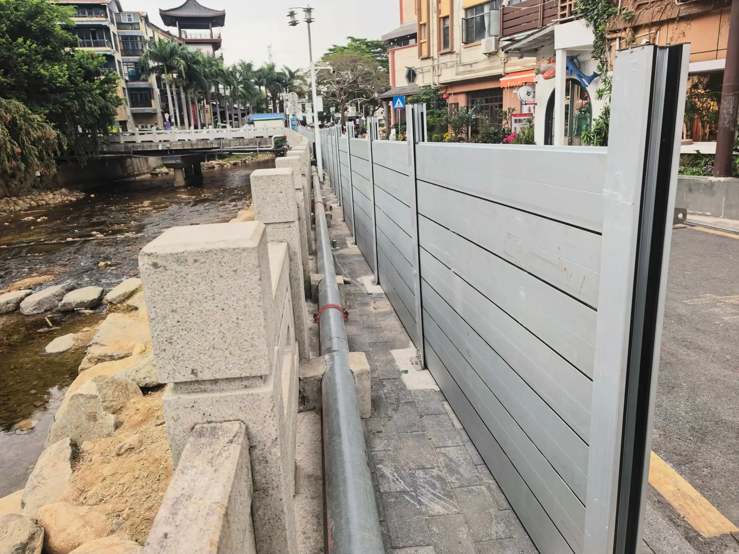
A REAL PROJECT · 55.12 IN PROTECTION
A continuous flood boundary.
A modular aluminum system.
See how individual panels and posts come together along an existing riverside walkway.
The supplied project information identifies this as a 55.12 in configuration. The two views show the river-facing side and the street-side supports. These installation photos illustrate the arrangement; they do not establish a tested water depth for another site.
- Stacked panels form the protective boundary.
- Repeated posts divide the run into manageable sections.
- Braces support the installed arrangement where specified.
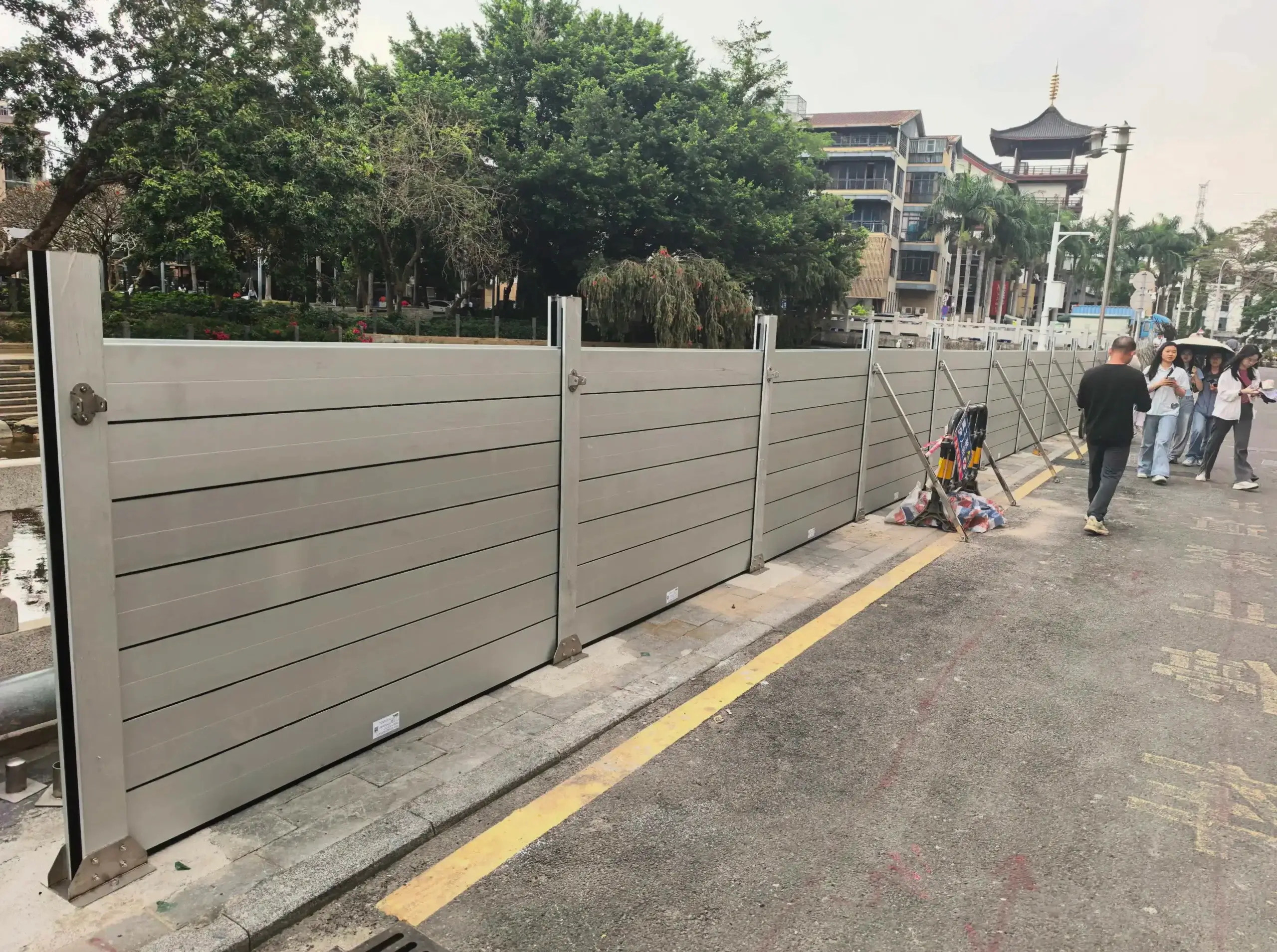
THE SUPPORTING SIDE
Plan the space behind the barrier.
Post positions, base fixings and any diagonal braces are part of the layout. Allow room for supports, panel handling and access before finalizing the flood boundary.
The photographed barrier is 55.12 in high. A 78.74 in configuration requires its own review of the spans, supports, fixings and applicable performance evidence; the photograph does not extend the project’s height or test conditions.
PROJECT VIDEO
See a completed Eudore project.
View the installed panels, posts and supporting arrangement. Use the footage to discuss access and layout, then confirm the documents for your own proposed configuration. Project footage is not a water-test report for every height in this range.
Get my free quote →Open video on YouTube ↗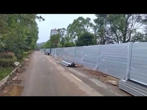
THE 55.12–78.74 IN SYSTEM
Panels and posts designed to work together.
This range pairs a 2.76-inch panel profile with 3.62-inch-wide side posts and project-specific intermediate supports. Confirm the connections, panel spans and support positions together with the proposed height.
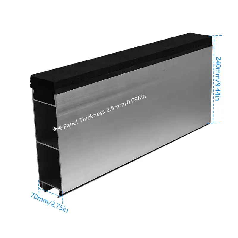
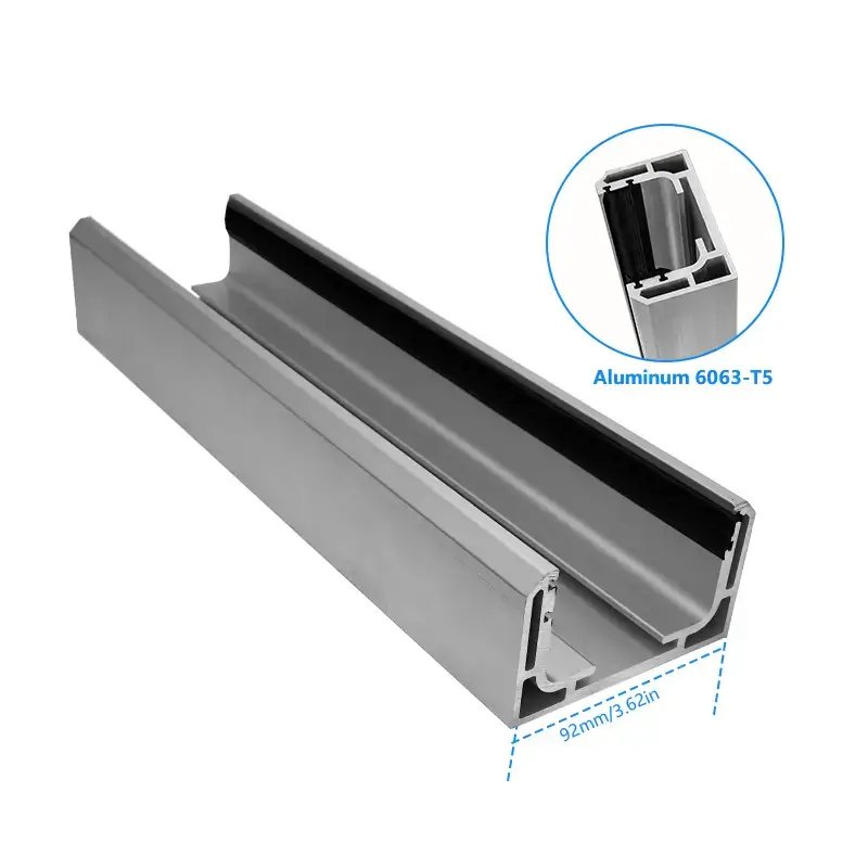
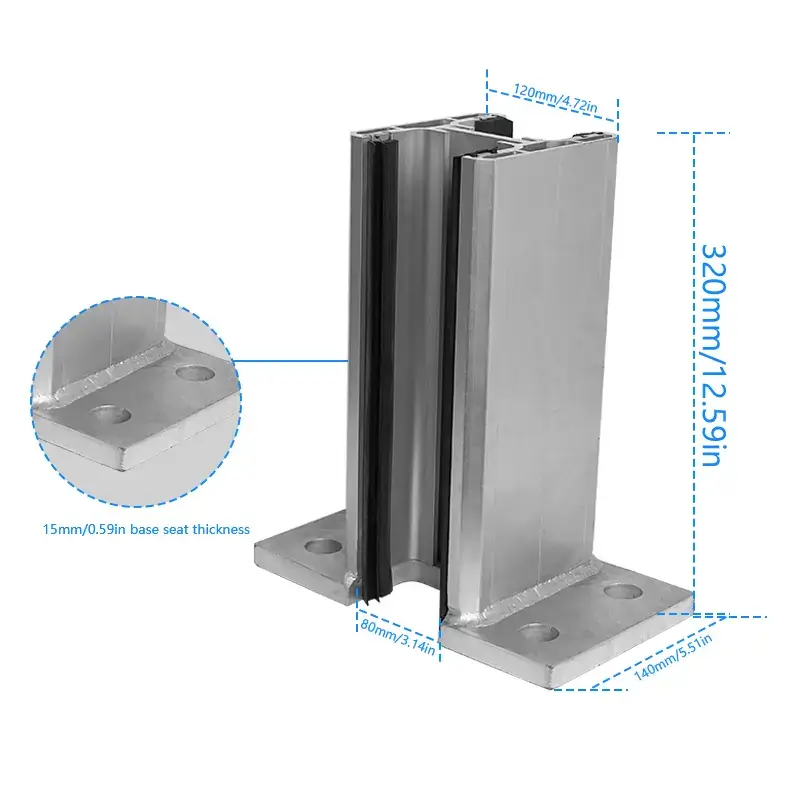
Reported DSC-095 Test Results
Three conditions from the commissioned report are summarized here for quick review. Open the original PDF above for the complete test method, sample details and limitations.
Final protection height and performance require opening-specific configuration, suitable structural conditions and correct installation.
Reported Results at Three Test Heights
Report BB1JZL-20250032 · Sample WBa20250423002a1 · 6063-T6 · 7,000 × 1,200 × 40 mm
The report concludes that the recorded column and water-deflector stresses were below 215 MPa and the recorded column deflections were below 5 mm for the tested sample and conditions. Opening-specific engineering and installation remain necessary.
FACTORY-DIRECT
See Where Eudore Flood Barriers Are Made
Eudore works directly with the Shenzhen manufacturing team for aluminum processing, custom dimensions, quality control, lead times and project-specific support.
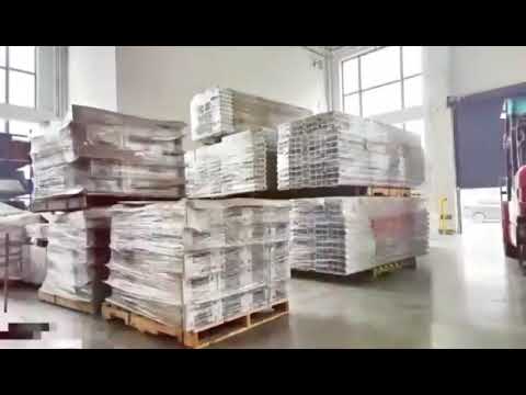
Aluminum Flood Barriers Factory Showcase
See the manufacturing environment, finished barrier inventory and production workflow behind the made-to-order system.
Open on YouTube ↗
Precision Cutting & Custom Flood Barrier Sizing
Watch aluminum components being processed for the custom dimensions required by residential and commercial openings.
Open on YouTube ↗

*Where applicable, based on order specifications. CE certification, RoHS documentation and third-party test reports are available for review.
CONFIGURATION AT A GLANCE
Specify your height.
Then resolve the details.
Review the requested height, clear opening or run length, supporting structure and proposed installation method together. Confirm the documented water conditions and allow space for any required posts, braces and panel handling.
FROM MEASUREMENTS TO DEPLOYMENT
Define the flood boundary
Share the opening width, required height, location and clear photographs of the mounting surfaces.
Review posts and supports
Coordinate the panel spans, foundation, wall connections and space for any required braces.
Install and check the system
Follow the approved installation details and check panel alignment, seals and compression.
Prepare for repeat deployment
Plan panel storage and handling, inspect the seals and rehearse deployment before flood conditions arrive.
PROJECT QUESTIONS
Plan your 55.12–78.74 in flood barrier.
Start with the protection height, the opening or boundary dimensions, and the supporting conditions at your site. These answers explain what is shown on this page; the final configuration is reviewed for the individual project.
Can the barrier be configured to 78.74 inches high?+
This model range is offered in configurations from 55.12 in to 78.74 in high, approximately 1.4–2 m. Confirm the selected height, panel spans, supporting structure and fixings with applicable evidence. The reference reports on this page do not by themselves establish performance at the 2 m upper limit.
Is the riverside project shown here 78.74 inches high?+
No. The riverside project shown on this page is 55.12 in high. It illustrates the panels, posts and rear braces in a completed installation.
Can it protect a long boundary or a wide entrance?+
Longer runs can be reviewed as sections with intermediate posts. Send the total length, changes of direction, surface levels and access requirements so the end connections, panel spans and supports can be resolved for the site.
What support layout does a 78.74 in flood barrier need?+
The support layout is determined from the required height, span lengths, mounting surface, base fixings and available space for posts or braces. A 78.74 in configuration should be reviewed for its own site conditions.
Can the panels be removed between flood events?+
Yes. The modular panels can be removed and stored. The installation layout determines which supporting components remain in place.
What information do you need for a quote?+
Send the clear opening width or total run length, proposed height, project location and photos of the floor, walls and available support space. Include drawings and documentation requirements when available. Ask the quote to identify the selected model, billable dimensions, supports, delivery and installation scope.
What is the price for this model range?+
Eudore confirmed the higher manual model rate as US$899 per square yard on October 27, 2026. It is not a flat price per opening. Confirm the model, billable area and included services in writing. The 78.74-inch boundary also appears in the higher panel range, so identify the quoted configuration before selecting a rate. See the price calculation guide for area examples.
Tell us about your opening
Share the opening type, clear width or run length, proposed height and project location. Include mounting-surface photos, available support space and any required documents so the team can review the configuration and quotation.
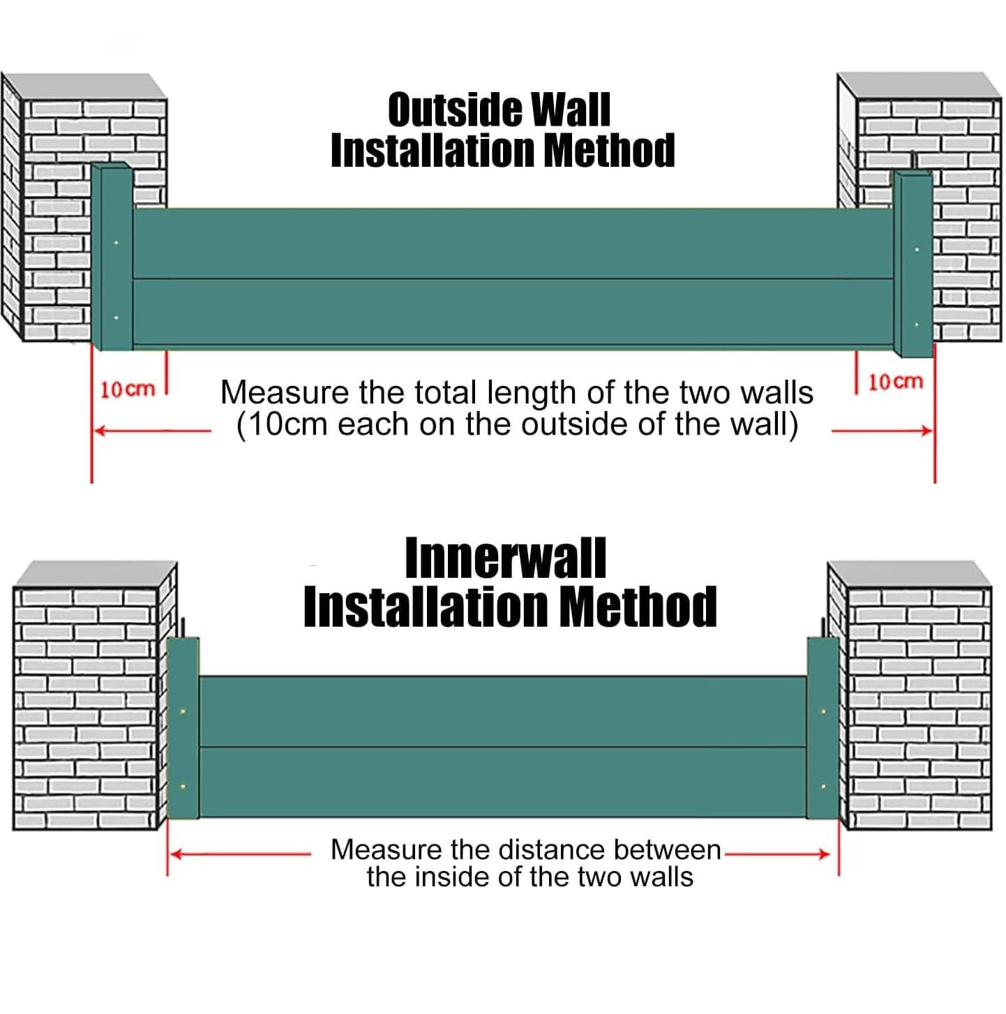
Record the actual opening width and proposed height. Photograph the jambs, floor and space for supports; ask the supplier to confirm finished panel dimensions and billable area separately.
TECHNICAL RESOURCES
Review the details before you specify.
Use the standard documents as references, then confirm which sample, material, dimensions and support arrangement they cover. Request the specifications, applicable performance evidence and installation details for the configuration being quoted.
Technical specifications
Standard product specification sheet
Open resource ↗02 / REFERENCEInstallation manual
Post positioning, assembly and sealing
Open resource ↗03 / VIDEOInstallation video
Watch the standard system installation
Watch video ↗04 / REFERENCEStructural calculations
Standard product engineering reference
Open resource ↗05 / REFERENCEProduct brochure
Standard product range and features
Open resource ↗06 / REFERENCETest report
Published standard product test results
Open resource ↗These links currently reference the standard product. The published test report applies to its stated sample and test conditions; it does not by itself establish performance for a 78.74 in configuration. Specifications and structural calculations for the selected project must match the final design.